Design brief: 3D printed casting of 3-foot long robot arm
Written by nTop
Published on May 4, 2021
3D printed sand casting molds and cores are changing the way high-performance, large metal parts are manufactured today. Additive manufacturing is enabling modern foundries to produce complex metal parts in rapid lead times. This article explains the benefits of coupling advanced design tools with 3D printed sand molds using, as an example, the redesign and manufacture of a 3-foot long robotic arm.
Watch this short video to learn more about this project.
Press the play button to watch the case study video.
Sand casting and industrial 3D printing
Metal casting is a common and well-proven manufacturing method used to produce goods that we incorporate into our daily lives. 90% of all manufactured products and machinery today include components made using casting. The most popular metal casting process is sand casting; over 70% of all metal parts are manufactured using this production process.
The sand casting process begins by creating a sacrificial mold that consists of compacted sand mixed with a binder. The mold’s cavity is then filled with molten metal through a gating system before the mold is destroyed to release the cast part.
Large sand casting mold ready for use after 3D printing and cleaning.
Sand casting dates back to the 1st century BC. Over the centuries, it has evolved into the industrial process we know. Yet, foundries today are further enabled by the advent of digital manufacturing and 3D printing technologies.
Sand casting using 3D printed molds and cores is emerging as a key industrial application of additive manufacturing. Until recently, design engineers and casting foundries used this hybrid manufacturing technology primarily for prototyping. Today, more and more foundries in the US and overseas are adopting this manufacturing technology to augment their internal processes.
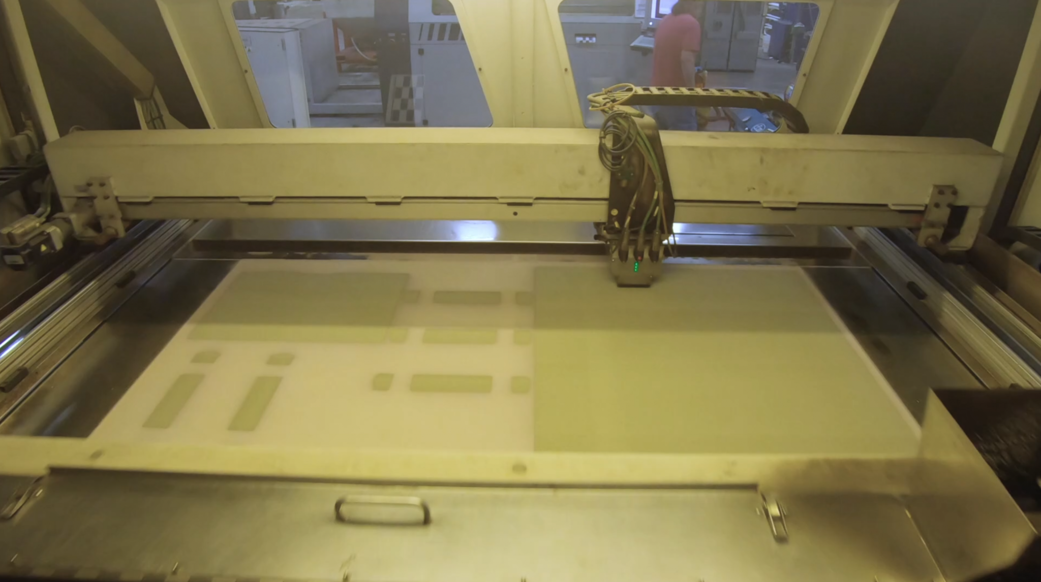
3D printed sand molds and core are manufactured layer-by-layer directly from a digital file in an industrial 3D printing system. The print head jets droplets of binder material over thin layers of sand to create each cross-section.
Benefits of sand casting with 3D printed molds and cores
Here are some of the ways that 3D printing can benefit a casting foundry:
- 3D printed sand casts and cores facilitate the creation of gating systems and risers that result in high-performance metal parts with fewer internal defects and up to 15% higher material strength.
- Additive manufacturing eliminates the need for hard tooling and casting patterns and the associated geometry restrictions. This benefit facilitates the production of high-performance, optimized parts with complex geometry.
- 3D printing and other digital manufacturing technologies help transform the image of the traditional foundry, attracting young talent and new workforce to the field.
Limitations of sand casting with 3D printed molds andores
However, 3D printing is only a tool. The limitations of this new technology in regards to sand casting include:
- Part design should still follow the restrictions imposed by the casting process and the 3D sand printing systems. These design considerations include wall thickness, changes in part cross-section, and wall-to-wall thickness.
- The current availability of industrial sand 3D printers is limited, and the cost of manufacturing 3D printed molds are relatively high. For reference, sand 3D printing costs approximately $0.1 per cubic inch, while a traditional foundry usually charges between $10-20k for a mold.
- As with every new technology, access to knowledge and design expertise is still limited. Elusive best practices and design guidelines stop engineers and manufacturers from getting the most out of this new technology.
The following case study directly addresses the last point. By documenting the design method and practical considerations that went into each decision, we hope to make this technology more accessible to manufacturers, designers, and engineers.
Case study: Topology optimized robot arm
To demonstrate the benefits of sand casting with 3D printed molds and cores, the engineers of nTop, Penn State University, Flow 3D, and Humtown joined forces to redesign a meter-long robotic arm. Together they created an end-to-end digital casting workflow — from part optimization to design for manufacturability and, finally, manufacturing.
Exploded view of the metal casting mold assembly.
The team combined cutting-edge design techniques, like topology optimization, with advanced casting features that can only be manufactured additively (including the sprue, gates, and risers). Using this method, the team managed to:
- Reduce the weight of the part by 40%
- Avoid common casting defects
- Directly 3D print the entire sand mold
- Manufacture the part in less than a week
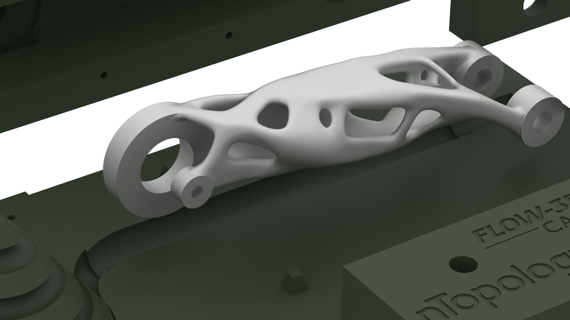
Generating a lightweight robotic arm
The first step in this project was to optimize the geometry of the robotic arm. Using topology optimization software, the team reduced the weight of the part by 40% — from 240 lbs down to 165 lbs — while still fulfilling the functional requirements of the defined loading conditions.
Topology optimization is a simulation-driven design technique used to maximize stiffness and minimize weight in aerospace and automotive engineering applications. The automated smoothening and reconstruction capabilities of nTop enabled the team to make design changes quickly and with little effort.
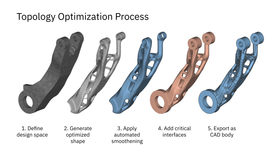
Overview of the topology optimization process in nTop — from original design to final export as a CAD body.
Of course, the engineering team considered the manufacturability of the part during the design phase. The final metal part weighs 165 lbs (or approximately 75 kg) when cast in aluminum and has bounding box dimensions of 39” by 16” by 16” (or 1.0 m by 0.4 m by 0.4 m). The robotic arm’s size limited the options available to the team to produce this huge part.
Following the traditional mold-making method (using a master pattern) would introduce several complications. Due to the complexity of the geometry, the design team would have to make many compromises, reducing the performance of the part.
Optimizing the design of the cast
To demonstrate the capabilities of the technology, the team decided to directly 3D print the entire mold. A more common production scenario would be to 3D print only parts of the mold, like the mold’s cores or other critical-for-quality systems.
This decision enables the team to optimize other critical features of the mold, like geometry and location of the sprues, gates, and risers. This process ensured the metal cast would have minimal internal porosity and high-performance material properties.
The mold was designed through a collaborative effort between Penn State University and Flow3D. The team took two main design requirements into account during this step:
- The molten metal must fill the cavity as smoothly as possible. Research has shown that flow rates below 0.5 m/s are necessary to minimize turbulence and reduce the possibility of material defects due to oxide layer detachment and porosity.
- The risers must solidify after the part.Uneven solidification is another common cause of internal defects, shrinkage, cracking, and part deformation. For this reason, the sections that will be machined off the part after casting must solidify last.
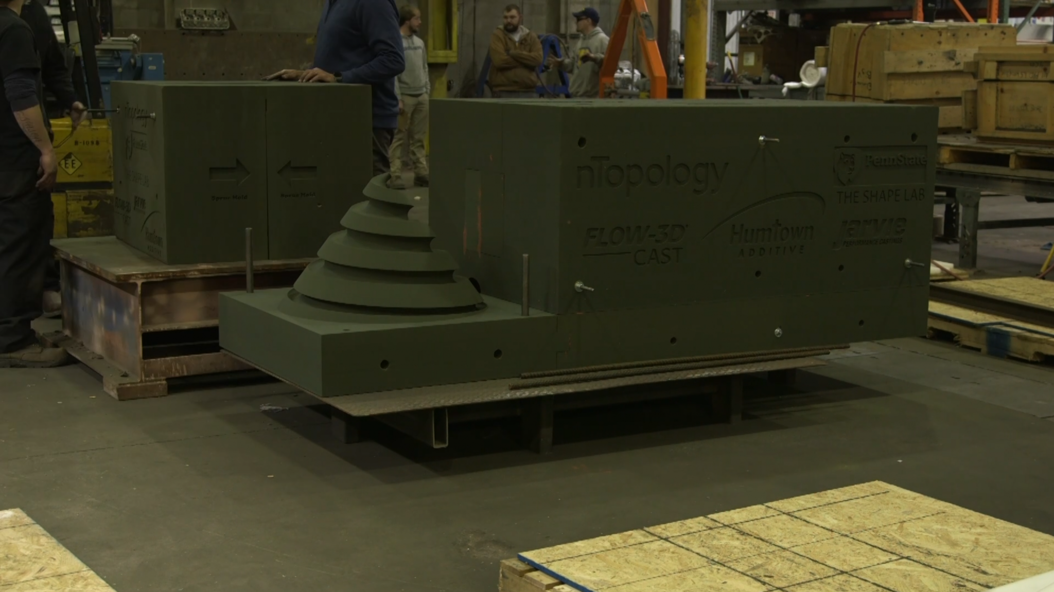
The mold was manufactured in parts and then assembled before pouring the molten metal. This design of the spiral helix sprue could not be manufactured with traditional patterns.
To ensure that the material would fill the mold without introducing turbulence, the team reimagined the design of the gating system and the risers. Instead of a down sprue, they used a spiral helix probe. Instead of cylindrical risers, they opted for risers with a spherical or hemispherical shape.
This optimized sprue and riser geometry ensured that the flow speed of the molten metal is below the desired threshold and that the molten metal would solidify evenly. Moreover, these features could only be made using direct additive manufacturing technologies, as it is impossible to create such tooling using a traditional casting pattern-making process.
The simulation of the casting process helped the team to ensure that the speed flow was kept below the critical threshold of 0.5 mm/s.
To determine the best part orientation and the optimal position of the runner, gates, and risers, the team ran multiple design iterations using casting simulation software. The goal of the simulations was to optimize riser performance, minimize porosity, and verify gate flow velocities. The simulation stage ensured that the part would be manufactured first-time-right and reduce the development time from months to weeks.
The unique direct production capabilities of the 3D printing process enable the production of these advanced mold design methodologies. They are also proven to yield significant performance improvement. Research has shown that, compared to traditional methods, cast parts produced using this model have:
- 99% lower defects for a total of 0.02% internal non-metallic inclusions
- 8 to 15% higher strength when cast using the same materials
The improved performance of the as-casted materials makes this process most relevant for foundries that create high-performance or custom parts.
Streamlining the manufacturing process
The ability to quickly produce the desired complex shapes and structures necessary in sand was fundamental to the part’s manufacturing to meeting the project’s goals.
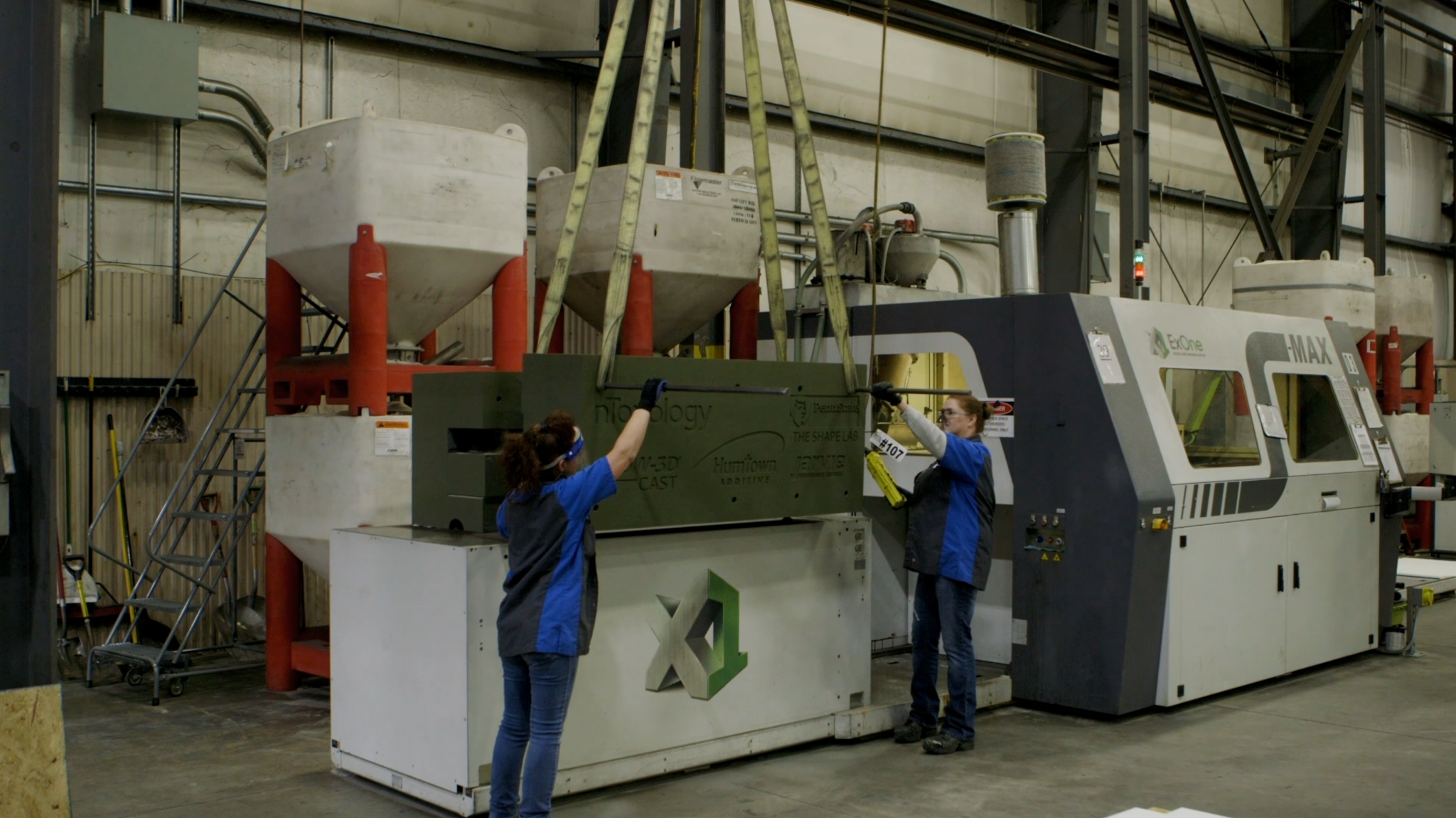
Humtown used one of their four ExOne SMax sand binder jetting 3D printing systems to the mold. Once the engineers of Humtown received the final mold design, they were able to print the mold in less than 24 hours. Due to their close partnership with Humtown, Trumbull Foundry was able to cast the mold within one day.
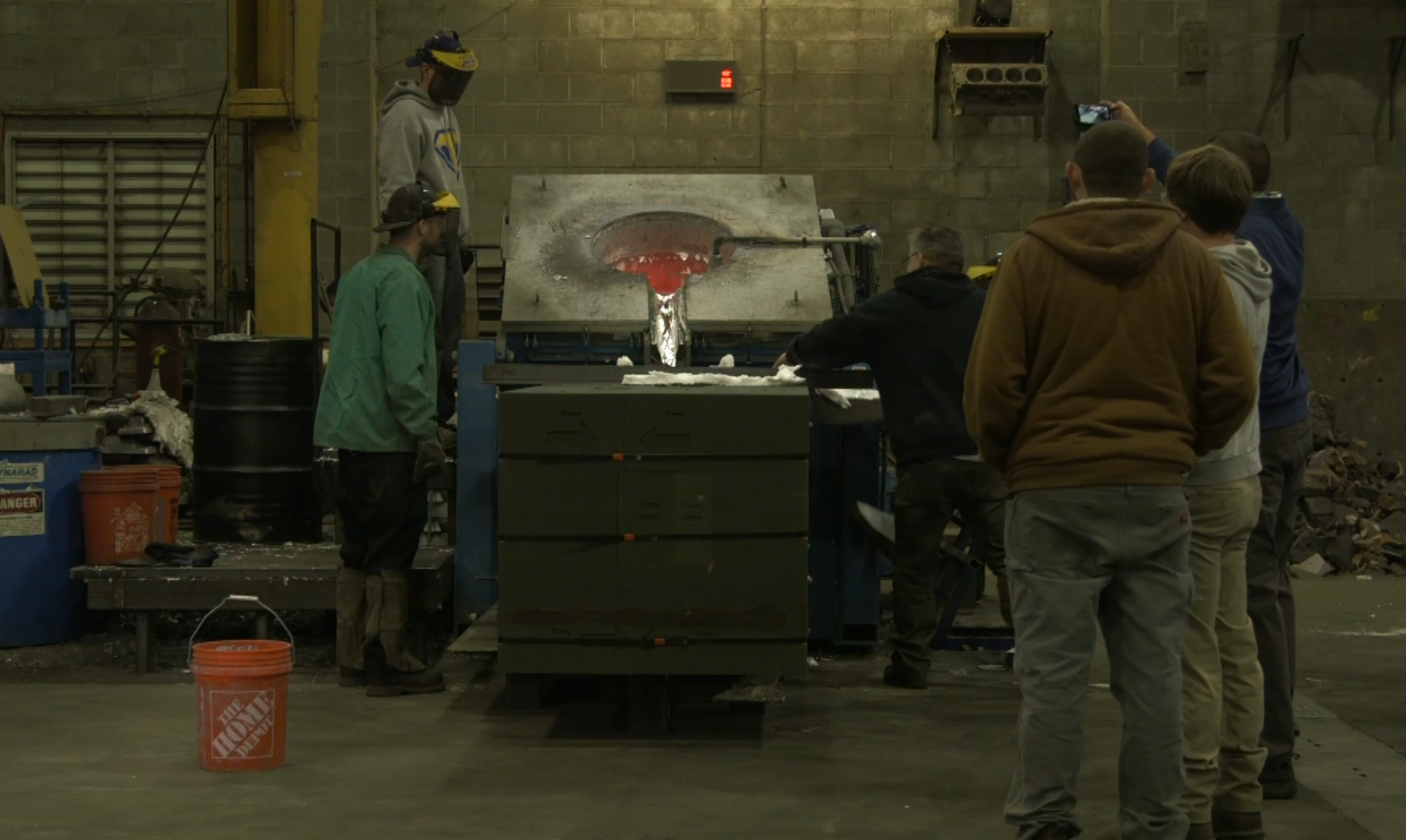
The process of pouring the molten metal into the 3D printed mold is identical to the sand casting process that takes place in any traditional foundry.
Humtown is one of the leading solution providers of 3D printed sand casts in the US. They have embraced new technologies and they now encourage other foundries to adopt new casting methods to create a lean and agile supply chain ecosystem.
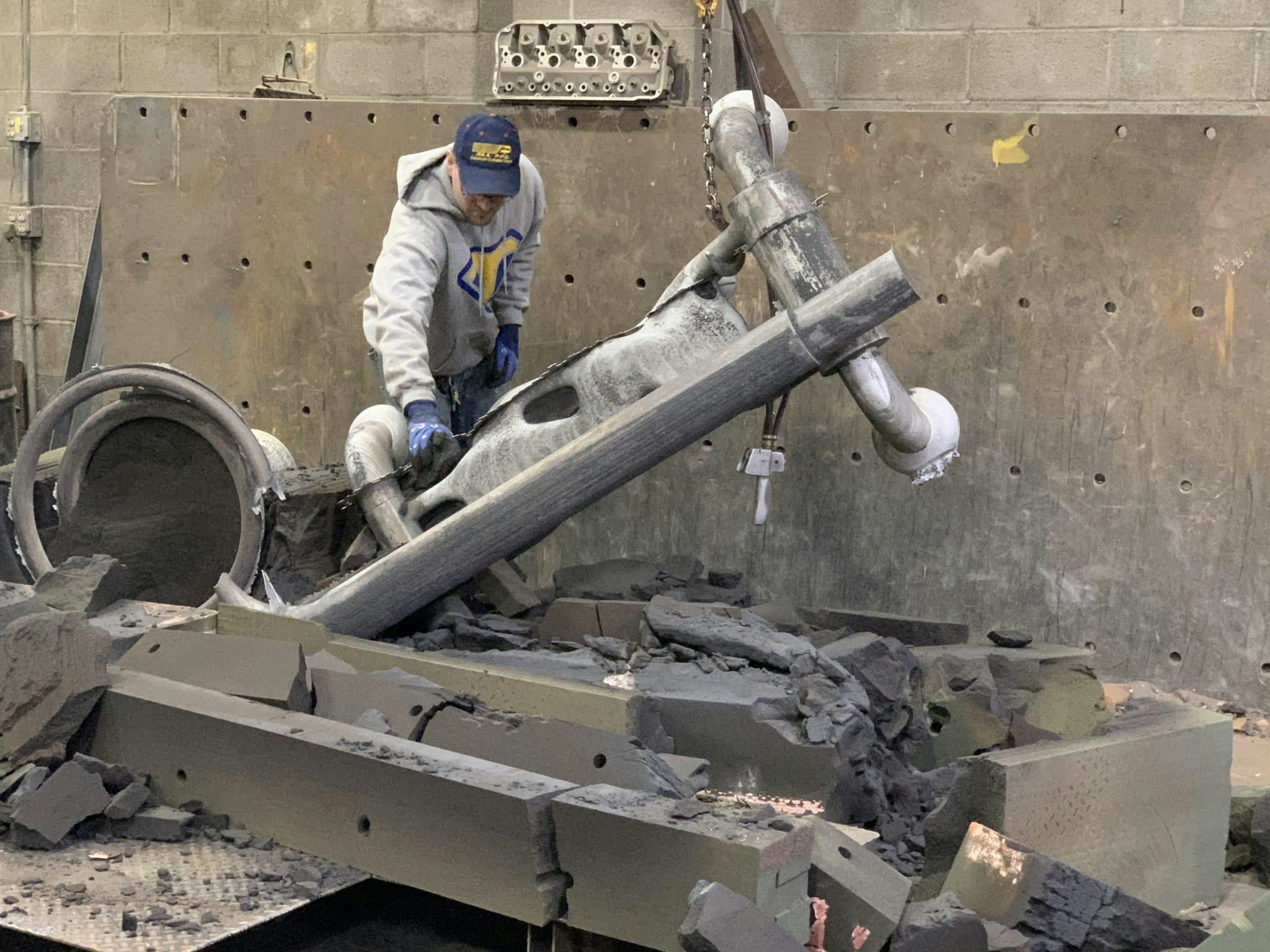
The mold was destroyed after casting to release the metal part which is now ready for post-processing operations.
Key takeaways
3D printing technologies are changing the scenery of metal casting. 3D sand printing enables design and manufacturing engineers to:
- Produce optimized large parts with complex geometries
- Design casting molds that minimize internal material defects
- Build leaner and more agile manufacturing supply chains
List of additional resources

nTop
nTop (formerly nTopology) was founded in 2015 with the belief that engineers’ ability to innovate shouldn’t be limited by their design software. Built on proprietary technologies that upend the constraints of traditional CAD software while integrating seamlessly into existing processes, nTop allows designers in every industry to create complex geometries, optimize instantaneously, and automate workflows to develop breakthrough parts and systems in record time.
Related content
- VIDEO
Scalable Parametric Workflows in Turbomachinery

- VIDEO
When your design changes, how fast can you respond?

- VIDEO
Creating a computational design workflow to lightweight drone panels with nTop’s new ribbing tools

- WEBINAR
Accelerating Product Engineering with Computational Design

- CASE STUDY
Reducing weight to help win and withstand the rigors of a 24 hour Le Mans race
