How to design high-performance filters for additive manufacturing
Written by nTop
Published on May 6, 2021
Filtering contaminants from high-temperature and high-pressure flows can often justify the use of additive manufacturing, especially when the performance enhancements provided by advanced design techniques are considered. This article demonstrates this through two design examples and describes how these techniques can apply to other applications, such as boosting reaction rates in catalytic processes.
Introduction
Filters are used in an abundance of applications to remove contaminants from a fluid or granular mixture. Whether these contaminants are rust or dirt in a fuel line, particulates in an air supply, or just coffee grinds in your morning brew, the general objectives and mechanisms are the same: block particles of some size while minimizing the disruption of the flow which carries them. Performance metrics of interest are often flow rate or pressure drop.
Currently, using additive manufacturing for filters applies primarily to high-pressure and high-temperature applications, especially when manufacturing with conventional methods requires multiple steps. Some suitable applications of 3D printed filters include the filtration of molten alloys during casting and the filtration of fluid for high-temperature and high-pressure hydraulic systems.
Filters are an excellent application for additive manufacturing and generative design because, in many cases, they play precisely to the strengths of these two advanced engineering techniques: intricate geometry for custom or tailored applications.
This article will showcase two examples of tailoring this intricate geometry to achieve filtration design goals.
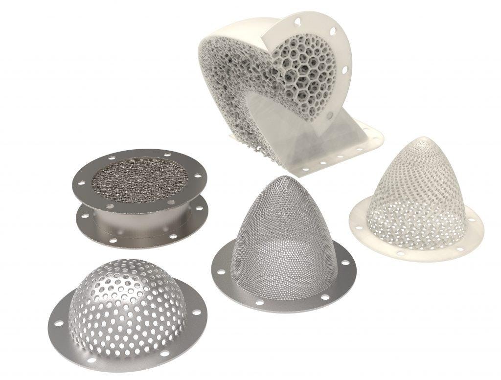
- Example 1: Surface Filter — A thin surface-style filter designed to block particulates of specific sizes while minimizing flow disruption.
- Example 2: Volumetric Filter — A volumetric filter designed to enhance catalytic rates while minimizing the part’s mass and material usage.
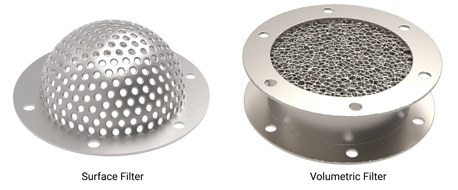
Figure 1: Two styles of filters discussed in this article. A surface filter (left) and a volumetric filter (right).
Surface filtration
With surface filters, the fluid or mixture only interacts with the part very briefly, so our design space is generally quite limited. Design freedom is limited to things like the overall filter geometry or the shape, size, or spacing of the holes. Getting serious performance gains from this short list of design variables can require us to get creative.
Design example: Reducing pressure drop
Here is an example of two design improvements to a conventionally manufactured hemispherical filter. The original filter in Figure 2(a) had 300 holes of equal size and spacing, drilled directly through the surface normals. It was designed to block contaminants of a particular size flowing through a pipe.
Simply 3D printing this conventional design would not utilize the full capabilities of additive manufacturing or modern design techniques. Here are two quick design improvements to enhance the performance of this filter.
Aligning the holes with the flow direction
First, the holes can be aligned with the flow direction, shown in Figure 2(b). We cannot make them all parallel to the flow since the filter is hemispherical in overall shape. Still, an algorithm can gradually attract the more orthogonal holes towards the flow direction.
Technical note: This algorithm works by defining an attractor vector v and a user-specified maximum adjustment angle θ (here θ = 40°). Holes perpendicular to the attractor vector v are rotated by the angle θ. Holes already parallel to v are not adjusted. Everything in between is proportionately adjusted by a knocked-down value of θ. This is an example of an algorithm to improve the design, not a mathematical optimization.
This modeling operation would be tedious in CAD, but it is simple with computational design methods. The computational design workflow is also undisturbed by significant changes to the shape of the filter. In other words, we can repeat the process with different filter geometries (like the conical shape in Figure 3).
This simple design change reduced maximum dynamic pressure and overall pressure drop by 15%.
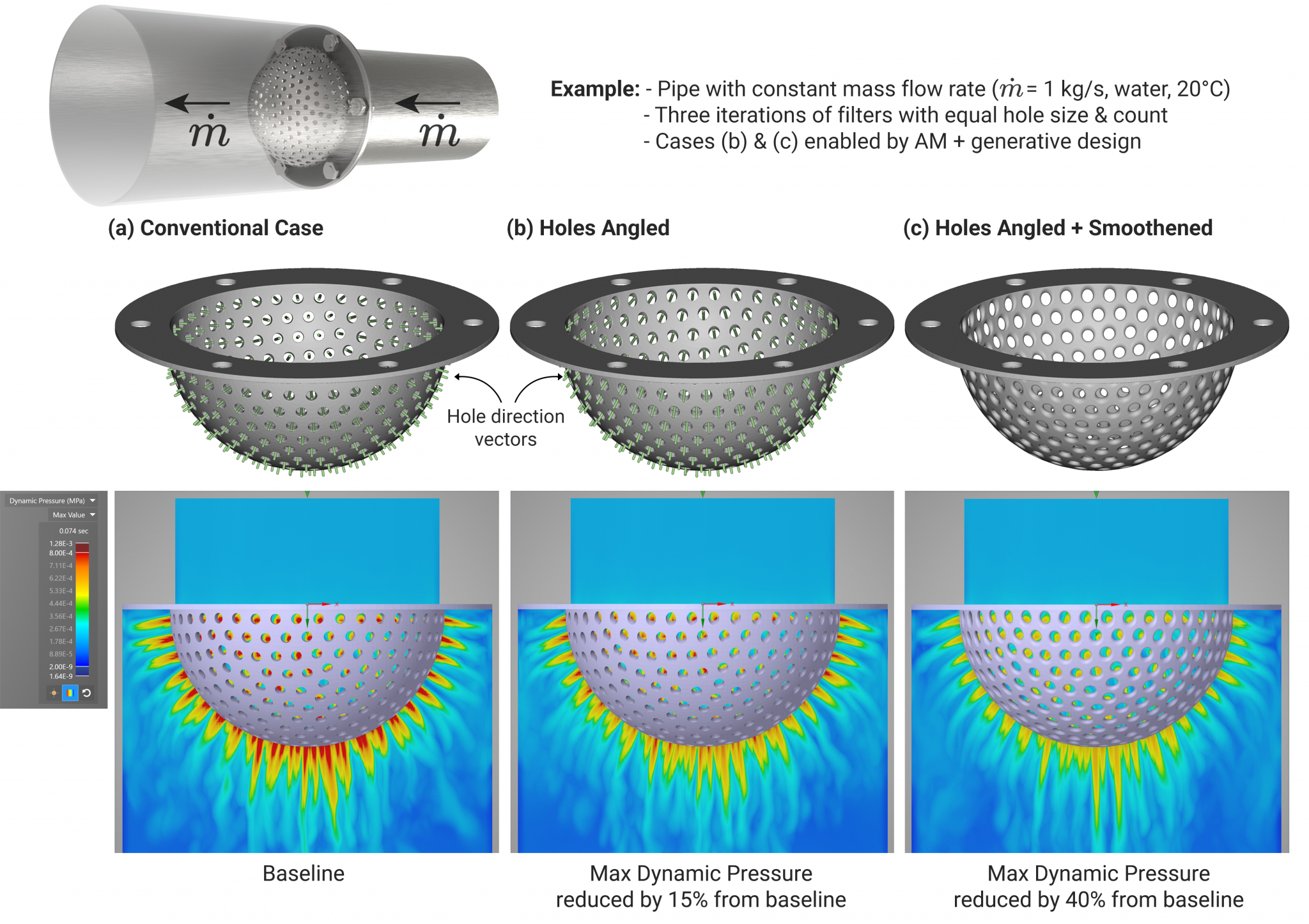
Figure 2: Design iterations of a filter with a constant mass flow rate of water at room temperature, simulated with Ansys Discovery Live. Maximum dynamic pressure was measured, and by conservation of fluid momentum can be interpreted as pressure drop. The two generative design steps significantly reduce the disruption of the flow compared to the conventionally manufactured baseline case.
Applying fillets to reduce pressure drop
Adding fillets to every hole of the filter — 300 holes that need fillets on both sides — adds many extra machining steps during manufacturing and a lot of clicking in CAD during design. Incorporating this directly into the 3D printed design can be done in one step with modern design tools.
Combined with the hole alignment, this simple design improvement reduced the pressure drop by a total of 40% compared to the initial design — see Figure 3(c) — with the hole count and hole throat diameters all still being equal. As a bonus, the iteration with smoothened edges also saves 6% weight and material.
Experimenting with different filter geometries
Aligning hundreds or thousands of holes (that may vary in size and spacing) with the flow direction, or applying these techniques to multiple parts of different shapes, can make the engineering process challenging. Engineers can greatly benefit from generative design with design automation in this area.
Figure 3 (a-f) shows several variations of this hole placement algorithm on two filter shapes, and Figure 3 (g,h) shows two alternative design routes using lattice techniques.
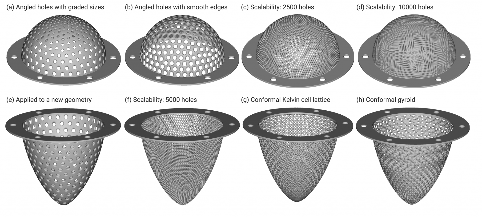
Figure 3: A selection of surface filter designs applied to two different filter shapes. The hole-drilling algorithm developed for the example in Figure 2 is applied to variations (a)-(f), and different lattice approaches are applied to variations (g) and (h).
Volumetric filtration
Surface area is a driving factor in many chemical, mechanical, and thermodynamic processes. The larger the surface area, the more material is available to participate in the reaction or process. However, maximizing surface area alone is not a well-defined optimization problem (the result would be an infinite-sized blob of material). It is crucial to precisely define these problems to apply generative design algorithms to them. With this in mind, the surface-area-to-volume (SA:V) is a better design variable than surface area alone.
This ratio is a driving factor in almost all transient chemical processes. It explains why sticks burn faster than logs, why leaves resemble flat thin plates, why grated cheese melts more quickly than a block of cheese, why cells in the body are small and numerous. It also explains why a good sponge has many small intricate internal passages and why the dust of otherwise innocuous materials like sawdust or flour can be so explosive. It is also relevant to a vast range of engineering applications from batteries to combustion to drug delivery and — of course — filtration.
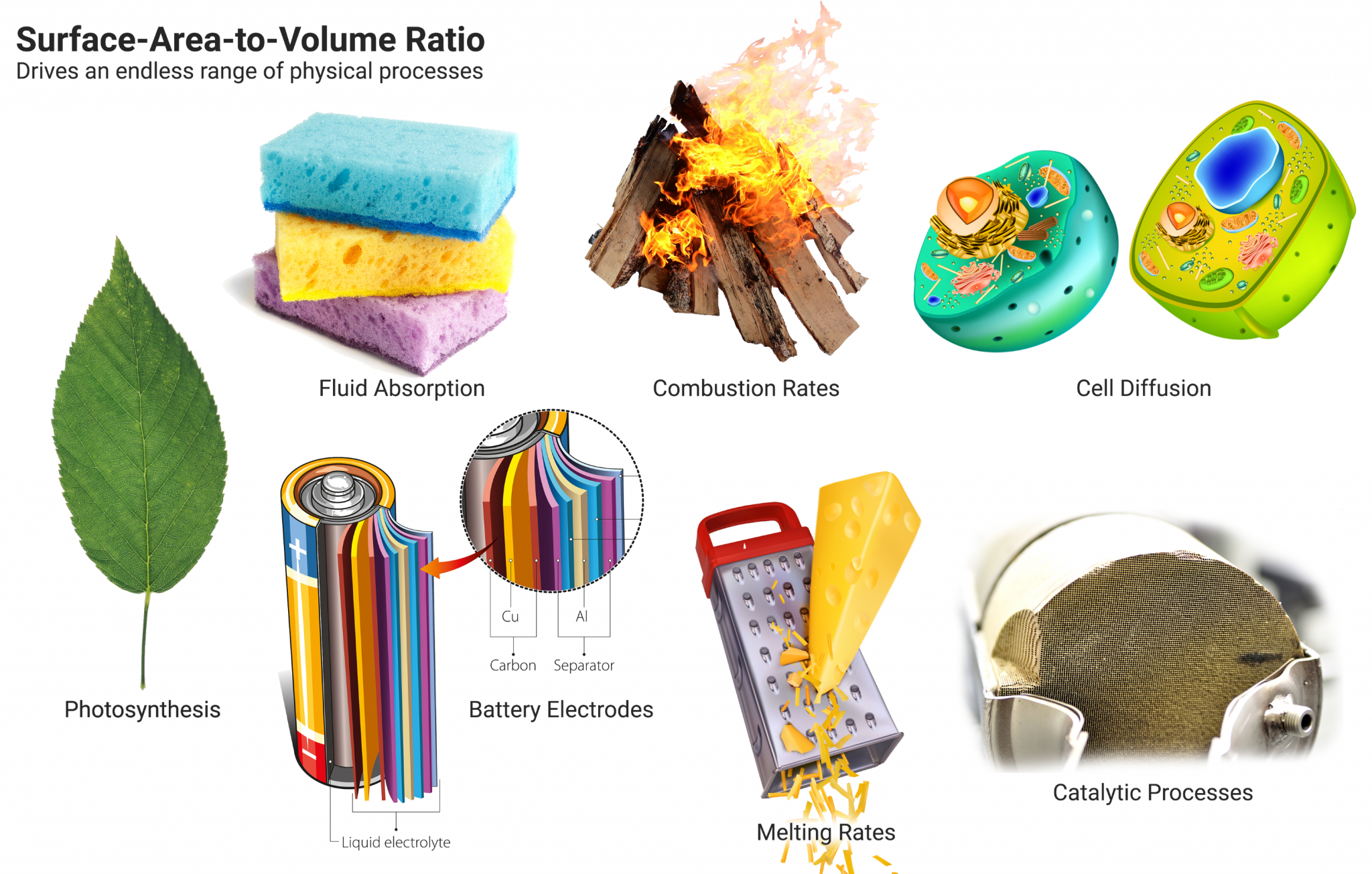
Figure 4: Surface-area-to-volume ratio plays a critical role in the function of many objects. It is the driving parameter for many physical processes, and therefore an extremely valuable design variable for engineers to have control over.
Application example: Catalytic converters
A typical example of a volumetric filter is the catalytic converter found in almost every modern internal combustion vehicle, ranging from cars to buses to trains. These devices clean the exhaust through a redox reaction, the reaction rate depending directly on the surface area.
Conventional catalytic converters consist of a ceramic honeycomb substrate with a metal coating acting as the catalyst. The metals used are typically platinum, palladium, or other similarly expensive metals, so it is essential to design an optimal substrate for the job.
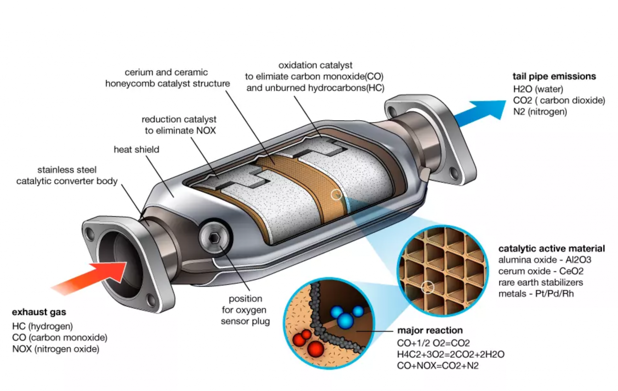
Figure 5: Schematic of a catalytic converter showing the square honeycomb substrate coated with rare earth metals. [Image Source]
Many engineers producing components for combustion engines ask the question: how can AM help us improve the performance of our designs?
What if you were able to produce any substrate geometry beyond that of the conventional square honeycomb? Or create a case with a form factor not restricted by the traditional drum-like shape shown above? Perhaps even incorporate the converter into the exhaust manifold where the temperature and operating efficiency are the greatest? These are now all possible with additive manufacturing.
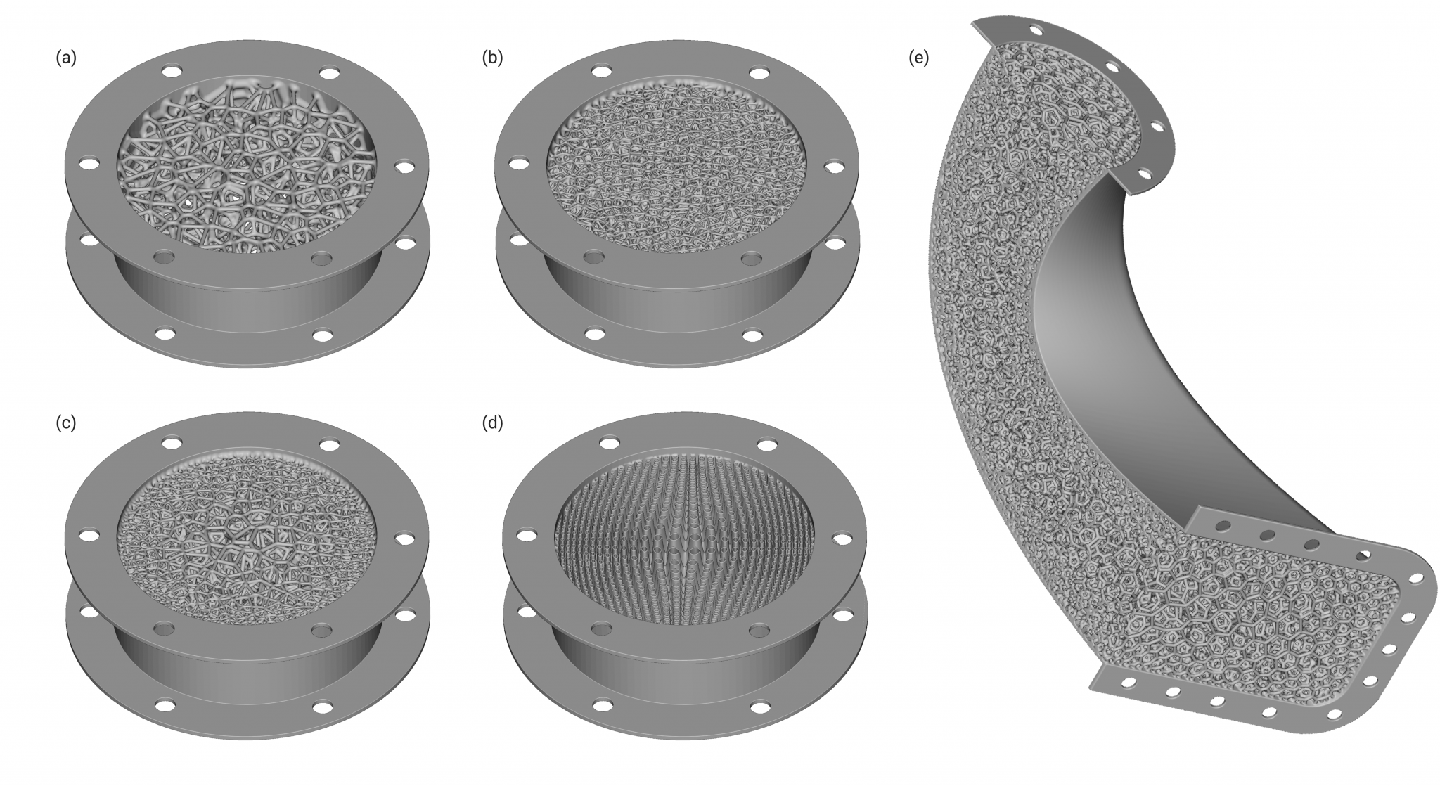
Figure 6: A range of volumetric filter designs in conventional form-factors (a-d) and integrated within a conformal pipe shown as a cross-section (e). Integrating catalytic filters into existing piping can reduce part count and weight and improve operating efficiency if located in higher temperature regions closer to the combustion source.
Defining key design metrics
When conducting initial design explorations or constructing generative design algorithms, it is helpful to identify design variables that depend only on geometry wherever possible and avoid variables that rely on expensive transient simulations. This method can significantly accelerate the initial design phase and reduce the number of simulations or experiments to conduct in future detailed design phases, saving time and money.
As explained above, the surface-area-to-volume ratio (SA:V) of an object is a determining factor in many physical effects. It can also be an excellent design variable to analyze when selecting a lattice unit cell for such an application. Is SA:V the full story here, though? Doesn't the fluid have to flow through this structure while minimizing pressure drop?
Technical note: SA:V is not a dimensionless property, so this means that it is often design-specific and scale-dependent. Engineers can consider using alternative unitless measures of compactness like sphericity or SA1.5:V where the exponent cancels out the units of length.
Incorporating some measure of how much the geometry obstructs the flow could also be helpful, but running dozens of fluid simulations in the early design phase can be burdensome.
One approach to doing this without running simulations in an initial design phase is the "shadowed volume" (see Figure 7.) We calculate it purely geometrically, taking milliseconds instead of minutes for a simulation. It is not a perfect metric since it assumes the ideal case of a ray-cast behavior (fluid particles moving only in straight lines) than actual fluid flow, but is fast to compute and provides a helpful preview when exploring a new design space.
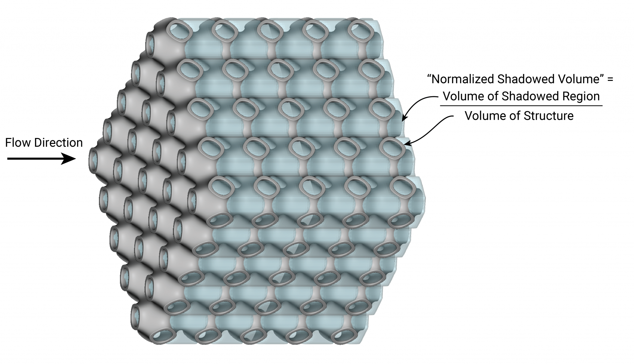
Figure 7: Definition of "shadowed volume." The shadowed volume is a unitless metric defined as the volume obstructed from the flow divided by the volume of the whole structure. It is a purely geometric calculation requiring no FE simulations.
Selecting a suitable lattice unit cell
Figure 8 shows a design exploration of several unit cells of equal relative density (i.e. mass) and their SA:V. We can quickly generate a ranking of different unit cells by our performance metrics to help guide our initial decision-making.
Here we can see that the TPMS-family of unit cells (light green) have a high SA:V ratio, while honeycombs (light blue) have a very low flow obstruction. Strut-based lattices (yellow) and stochastic foams (red) lie somewhere in between.
It would be up to the engineer to proceed with a few design candidates to a more detailed analysis phase, whether through CFD or experimentation. The relative importance of SA:V and the shadowed volume metric would highly depend on the fluid and flow rates in question, so these rankings are just intended as a workflow demonstration. In many engineering problems, such as those requiring mixing, a perfectly unobstructed flow may actually be disadvantageous — it is all about context.
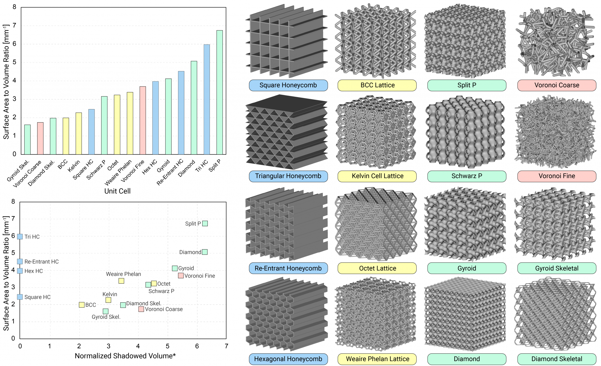
Figure 8: A design exploration of various unit cells of equal relative density, including honeycombs (blue), strut-based lattices (yellow), TPMS lattices (green), and stochastic foams (pink). The surface-area-to-volume ratio and the normalized shadowed volume are plotted.
While the above example is in the context of a catalytic filter, recall how widely applicable SA:V is to physical processes. A similar design process to that shown above could also benefit many other applications beyond filtration.
Key takeaways: Generative design and additive manufacturing
Most filters will continue to be produced by conventional mass-production methods, but numerous applications can benefit from the combination of generative design and additive manufacturing. Examples include:
- Fuel filters in high-performance aerospace or automotive engines
- Filters for high-temperature or high-pressure industrial processes (such as pouring alloys or filtering oil & gas)
- Filters that require highly customized geometry or materials (such as specific alloys or ceramics)

Figure 9: A range of filter designs rendered as different additively manufactured metals and ceramics.
Incorporating geometric design features otherwise infeasible with conventional tools can yield substantial returns in performance for relatively little design effort.
In the first example, aligning the holes of a filter and smoothening the sharp edges reduced pressure drop by 40% over the conventionally manufactured baseline part. We can then scale this design process to thousands of holes or to a variety of different part geometries.
In the second example, we constructed a design study to explore different lattice geometries for catalytic processes, uncovering the tradeoffs between surface-area-to-volume ratio and flow obstruction.
These two design methodologies are straightforward to apply using design tools like nTop.

nTop
nTop (formerly nTopology) was founded in 2015 with the belief that engineers’ ability to innovate shouldn’t be limited by their design software. Built on proprietary technologies that upend the constraints of traditional CAD software while integrating seamlessly into existing processes, nTop allows designers in every industry to create complex geometries, optimize instantaneously, and automate workflows to develop breakthrough parts and systems in record time.


