Lightweighting with implicit models
Written by nTop
Published on May 8, 2019
The ability to produce high-resolution geometry using implicit modeling opens a broad range of opportunities to tune the material properties of a part. Creating stiff, lightweight, and highly engineered parts is one of the most popular applications, and researchers are learning about new ones regularly.
The last blog post in this series introduced the idea of interpolation as a basic technique of working with implicit models. Let’s extend that technique to one of the most common applications of our platform: creating stiff, robust, and lightweight parts.
A brief introduction to lattices
With advanced manufacturing, we can now create structures at such fine scales that, from a design perspective, it feels like we are engineering the mechanical properties of a bulk material. Such fine geometry is often called “mesoscale” and the result is sometimes called a “metamaterial.” For the sake of generalization, we’ll use the term “lattice” to refer to any structure made from some fine pattern of material and air.
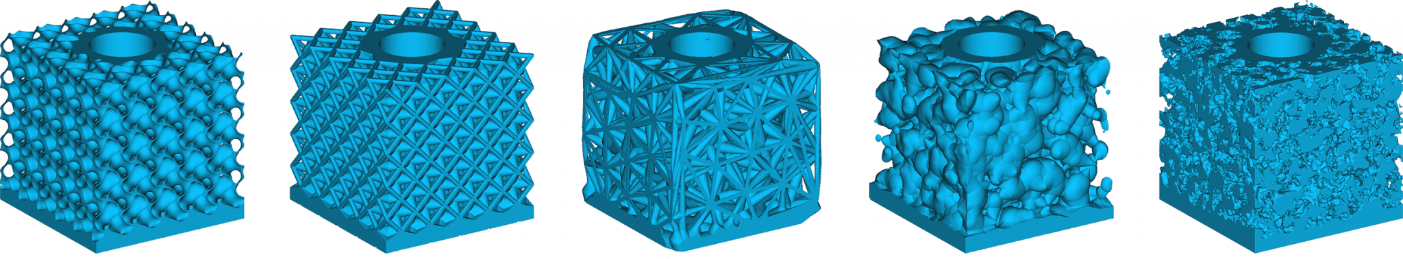
Five examples of lattices: a gyroid TPMS, an octet beam lattice, a stochastic Delauney lattice, cellular noise, and simplex noise.
Lattices can be chosen to manipulate a variety of more exotic properties than density, such as elongation, vibration damping, Poisson ratio, and electromagnetic effects. In general, lattices can be categorized as bend or stretch-dominated, open or closed, and periodic or stochastic. The lattices themselves may be warped to conform to geometry or engineering data such as stress or flow fields.
nTop offers a dedicated solution to analyze and control these structures in various applications. Let’s look at the general purpose modeling techniques that work on any fine-scale structure that is part solid and part air.
Lattices and density
As discussed earlier in the series, CAD systems are primarily concerned with the creation of solid models. Solids are made of insides and outsides, separated by a distinct boundary. Although the lattices we produce will also be such “black and white” solid models, during the design process, we can think of the models as grayscale as the lattice transitions from air to fully dense solids. Conceptually, 3D lattices are like halftone patterns in 2D printing, which vary saturation by modulating fine dot patterns of ink.
Lattices may be graded from solid to air. Often, a manufacturing constraint such as minimum beam or wall thickness limits the lightest range of the volume ratio.
To control density, we create functions that use a volume ratio field to modulate the implicit solid. To keep consistent, let’s normalize each lattice function so it ranges from 0 to 1, where 0 is air and 1 is solid. That means that we can fully drive our density by subtracting a volume ratio:
VariableLattice = BaseLattice - VolumeRatio
where both BaseLattice, our lattice function, and VolumeRatio ranges from 0 to 1. It’s helpful to think of BaseLattice as our “shape function” and VolumeRatio as our “modulation function.”
Applying lattices to CAD models
When applying lattices to real parts, there are typically three zones of the model about which we are interested:
- Solid regions of our part should be 100% dense, typically around mounting interfaces, aerodynamic surfaces, and known high stress regions.
- Lightweight regions are the main fill of our part, where fields drive an optimal lattice for a manufacturing process or loading condition.
- Optionally, some regions may open to air, creating another transition region.
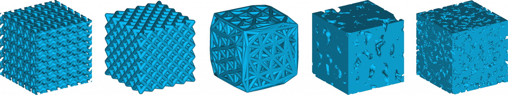
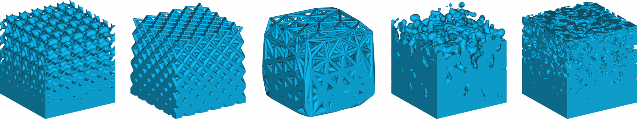
The five lattices shown above, applied to a block with a solid bottom and hole through it. These parts were created by selecting faces of CAD B-rep for solid treatment while the remaining regions were left open to air.
To create such a part, we set up of two stages of interpolation: from solid to lattice and from lattice to air. To apply our lattice to a shape, we use the shape to produce a volume ratio envelope as our lattice modulation function:
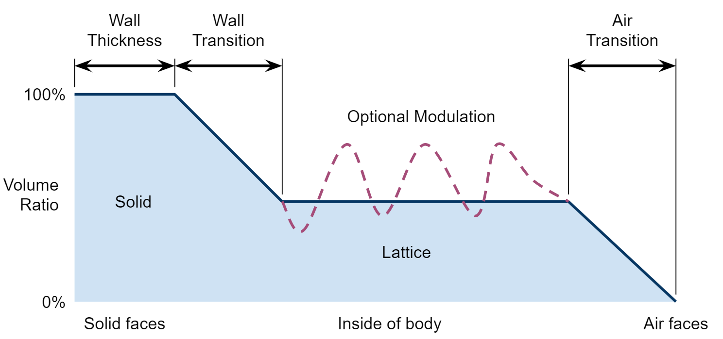
The volume ratio envelope is modulated by distance from faces of a body that are either specified as solid walls or air. Solid walls typically include a thickness parameter, and both phases transition to a nominal lattice in the inside of the model. Simulation results or empirical data can directly modulate the lattice region.
To incorporate simulation results, empirical data, or hand-modeled fields to control the lattices, one simply uses those fields to drive the volume ratio instead of leaving it constant.
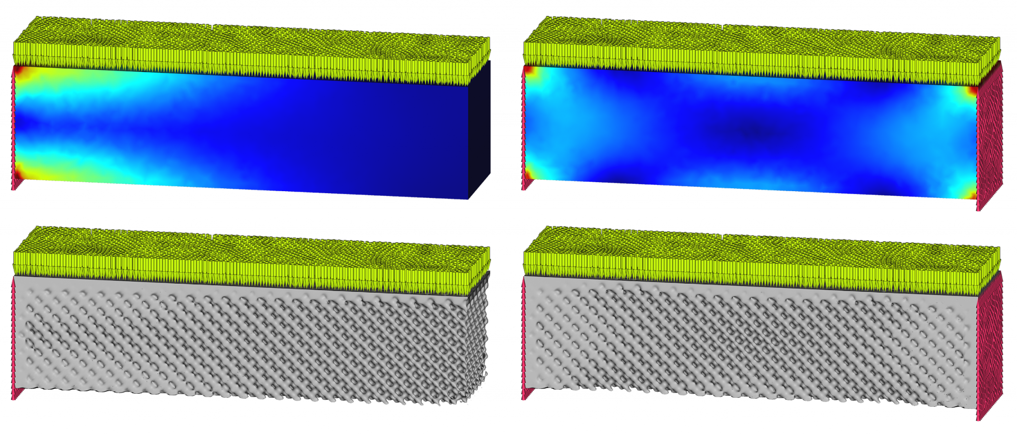
Two loading cases of a beam generate two fields that modulate a lattice, shown with two different cases. The local stress changes the beam thickness, and proximity to a load or boundary condition creates a transition to a firm, flat mating surface. Test specimens, such as the models created in nTop above, can confirm the theory in simple cases and then apply that knowledge to arbitrary part geometry from CAD with loading from CAE.
Summary
The ability to produce high-resolution geometry opens a broad range of opportunities to tune the material properties of a part. Creating stiff, lightweight, and highly engineered parts is one of the most popular applications, and researchers are learning about new ones regularly.
There are a wide variety of lattices and other structures that can produce mesoscale geometry, but one of the main properties to drive them is volume ratio. Using implicit modeling, that ratio can be locally adjusted from zero to full density based and controlled using simulated and empirical engineering data.
As an engineer creating a lattice, there are two functions to consider: the lattice function and the volume ratio function. Choose a lattice for its bulk material properties, and then modulate it using a volume ratio function based on CAD geometry and the engineering data fields. This approach makes it straightforward to capture engineering knowledge on test parts and directly apply the technique to complex CAD designs.

nTop
nTop (formerly nTopology) was founded in 2015 with the belief that engineers’ ability to innovate shouldn’t be limited by their design software. Built on proprietary technologies that upend the constraints of traditional CAD software while integrating seamlessly into existing processes, nTop allows designers in every industry to create complex geometries, optimize instantaneously, and automate workflows to develop breakthrough parts and systems in record time.


